
Week - 5 3D Printing and Scanning
Objective of the week:
ASSIGNMENTS
| Task |
| Group assignment: testing the design rules of the printers in the lab: Link |
| Explained what you learned from testing the 3D printers |
| Documented how you designed and 3D printed your object and explained why it could not be easily made subtractively |
| Documented how you scanned an object |
| Included your original design files for 3D printing |
| Included your hero shots |
Subtractive vs Additive Processes:
Additive manufacturing is the process of creating an object by building it one layer at a time. It is the opposite of subtractive manufacturing, in which an object is created by cutting away at a solid block of material until the final product is complete.
Technically, additive manufacturing can refer to any process where a product is created by building something up, such as molding, but it typically refers to 3-D printing.
How it works
To create an object using additive manufacturing, someone must first create a design. This is typically done using computer aided design, or CAD, software, or by taking a scan of the object someone wants to print. Software then translates the design into a layer by layer framework for the additive manufacturing machine to follow. This is sent to the 3-D printer, which begins creating the object immediately.
How do you 3D Print and what is 3D printing?
Opening the world of 3D Printing to beginners…
1. What Is 3D Printing?
3D printers are machines that fall into different categories. They are computer-controlled, also known as CNC (Computer Numerical Controlled) machines. Unlike subtractive manufacturing, where machines cut or drill parts out of raw material, 3D printers use additive manufacturing. This means that they add material bit by bit to create their work. In summary, 3D printers are computer-controlled machines that add material to create the shapes you want.
Compared to other CNC industrial machines, 3D printers are less efficient because they take hours to create parts, while machines like injection molding machines can produce stronger, more durable parts in minutes. Different 3D printers have their own advantages and disadvantages, but most of them produce relatively small and weak parts. So why use 3D printing?
3D printers are affordable, allowing anyone to easily create anything. They enable designers to bring their ideas to life quickly, iterate on designs rapidly, and create complex geometries with ease. In short, with just a button press, you can bring your imagination to reality.
2. Rapid Prototyping
Unlike most other CNC machines, 3D printers have very minimal associated setup costs or procedures. 3D printers can be used to produce custom designed parts relatively quickly and cheaply, making 3D printers one of the best rapid prototyping tools. Larger scale manufacturing machines may require precisely machined molds or fixtures for each new part, which means that they have more setup costs and steps required to produce content; they are set up to make hundreds or thousands of specific parts over and over again. Using a 3D printer, a part can be cheaply designed and made, and then its design can be modified, printed, and tested multiple times in rapid succession before the part reaches full scale production.
3. Intricate Geometries
3D printing is a hands-off manufacturing process; just by pressing a button, whatever you design will be made. Other manufacturing methods, like the drill press, lathe, or milling machine, need to be operated by the maker. The workpiece needs to be aligned, measured, and machined by the user, which introduces human error into the making of the part. 3D printers, because of the way that they create parts, can make many parts with intricate geometries, including natural shapes like prosthetic limbs or animal models, or more complicated shapes like polyhedra or scale building replicas. 3D printers open up a lot of opportunity to makers just because they allow people to make things they feasibly couldn't before.
4. Customized Content
As explained previously, 3D designs can be easily changed on the computer and then re-printed. This means that files can be customized for certain people or things, and printed easily, with no change to the setup of the machine. Being able to create personalized content is valuable for both small-scale manufacturing and for makers, because it allows them to create designs for specific people, or even produce designs that others give them. Personalized jewelry, custom fit prosthetics, and even 3D scans of people can be printed and modified to suit the end recipient.
5. How Does 3D Printing Work?
To understand how 3D printers work and how to design for them, you need to know the different types of 3D printers available. These printers construct parts by adding material layer by layer and fusing them together to create solid objects.
There are various types of 3D printing processes. Some are suitable for large-scale manufacturing, some allow for multiple materials or colors, and some are easy to build. This guide covers the most common types of 3D printers, although there are a few other types that are derived from these four.
6. Fused Deposition Modeling (FDM)
Fused Deposition Modeling (FDM) is a common and easy-to-understand type of 3D printing. In FDM, the printer melts down ABS or PLA plastic and deposits it layer by layer onto the printer bed. The layers fuse together as they cool.
FDM printers are popular for their affordability and ease of construction. The precision of these printers depends on the quality of the motors and the extruder head. However, printed parts may be weak along their horizontal cross sections due to the layer-by-layer construction. Overhanging sections require support material. FDM printers with multiple extruder heads can use soluble support material, while those with single extruders use less dense material that can be removed after printing. Multiple extruder heads also allow for printing in multiple colors or materials.
7. Stereolithography (SLA)
Stereolithography is the oldest 3D printing method, in which a laser is used to solidify liquid resin with ultraviolet light. While FDM printers draw out the layers of filament to form the 3D model, the laser beam on an SLA printer draws out a slice of the part to cure the liquid resin layer by layer, generating the 3D part. While most other 3D printers print from the bottom of the part and work their way up, SLA printers can print from the top down. The laser and resin bath sit at the base of the printer, and the part is fixed to the bottom build platform and is drawn up as it prints.
SLA printers can be very fast and precise because of their nature. However, the resin itself is expensive, and because it is photocurable, needs to be stored in specialized containers. Most resins, when they cure, are usually very brittle, and cannot withstand much force, so SLA printing is usually useful when it comes to prototyping, but not production. Like FDM printers, SLA printers require support structures for printed parts, but their materials are limited because they can only print in cured resin, and cannot print multiple material types at once. However, the precision of SLA printers allows them to print very intricate, delicate structures.
8. Selective Laser Sintering (SLS)
Selective Laser Sintering is very similar to stereolithography in that a laser is used to solidify material and form a solid shape. The biggest difference between the two technologies is that while SLA printing uses liquid resin, laser sintering cures powdered material, such as polyamides (PA), polystyrenes (PS), thermoplastic elastomers (TPE), and polyaryletherketones (PAEK). SLS 3D printed nylon parts are strong, stiff, sturdy, and durable. The final parts are impact-resistant and can endure repeated wear and tear. Nylon is resistant to UV, light, heat, moisture, solvents, temperature, and water.
Layers of powder are laid down onto a print bed, and the particles of each layer are cured by a laser. Selective Laser Sintering is advantageous in that it can support a wide range of materials, including plastics, glass, and some metals.
No support material is needed to print parts on an SLS machine because the parts are immersed in power, so they can be used to create more complicated and precise parts than most other printers. However, they are usually only found in industry as they require high power lasers and can be very expensive.
9. Laminated Object Manufacturing (LOM)
In the Laminated Object Manufacturing process, a laser or knife is used to cut slices of the 3D model out of sheets of material. Each sheet of material is pulled over the previous sheet and cut out by the cutting tool, and then glue is laid down so that the next sheet will adhere to it. The printer thus generates stacks of sheet material cut out and fused together. Because LOM printers consist of stacks of paper, the paper can be printed on (in 2D) before used on the machine, meaning that these printers can actually be used to create colored 3D printed artifacts.
These printers have very low production costs because the raw materials are just reams of paper or plastic. They have the benefit of printing flexible, strong parts because of the material properties of the sheets. While the parts are strong, they are just stacks of paper, so they tend to wear easily and small part features can easily be peeled open. LOM machines are best at creating large parts with minimal small details. Each print requires a lot of post-processing to remove the part from the rest of the material. These printers usually generate a lot of waste because each part needs to be dug out of stacks of paper and the geometries of the parts created are restricted due to the way parts are manufactured.
10. 3D Design for 3D Printing
3D printers allow designers to go straight from concept ideas and designs to physical models. In order to do so, the object needs to be designed on a computer using some sort of 3D design software. Once a part is designed, it can be imported into software specific to the 3D printer in use, which will slice the part and send the printer a list of paths and directions used to create the part.
There are many different CAD (Computer Aided Design) programs out there to design 3D models for a variety of purposes. Design programs like Tinkercad or Autodesk 123D are free and great for beginners interested in 3D design and 3D printing, while programs like SolidWorks and Autodesk Inventor are used by professional engineers to design parts and assemblies for production. I'll cover some of the considerations necessary when designing a part to be 3D printed.
11. Part Orientation
When designing for 3D printing, there are a few design guidelines and constraints that should be followed, as there are for any manufacturing process. One of the most important considerations during the design process involves designing with a build face in mind.
All printers start building the part from the print bed, so remembering what face the part is being printed from is important. While determining optimal part orientation is slightly different on all printers, designing to optimize that orientation will minimize material usage, print time, and risk of print failure.
Reducing Print Time and Support Material
By orienting your part well, you can reduce the amount of support material needed, which can minimize material and print time. Support material can be hard to remove and creates a rough surface finish, which isn't the best if you want your part to look like a finished product. In order to remove the effects of the support material, parts need to be polished and sanded down, which may affect the tolerances of your part if it is interfacing with something else.
Part Strength
On most desktop printers, parts usually tend to break along cross-sections of the part that are parallel to the build plate. Material is laid down or cured layer by layer, and the layers don't fuse as well as they do in higher end printers, creating seams along the cross-sections of the part. This means that parts can shear easily along those planes if force is applied. If you know how and where force will be applied to your part, orient your part such that the direction of force is not along those cross-sectional planes.
Build Adhesion
On most printers, primarily FDM machines, the 3D printed parts stick to the build plate as they are printing, and a very small contact area may result in the part falling off the build plate. The side of your part has the most surface area on the same plane is usually the side you'll want to print on, although this can change depending on the features of a given printer.
12. Overhangs and Arches
As I mentioned previously, most printers require printed support structures to hold up flat overhanging features of their parts. Because material is laid down layer by layer, most printers (primarily FDM and SLA printers) can handle up to about 45 degrees of overhang from the horizontal without requiring supports, and can also create features like vertical holes or round arches with minimal drooping. To avoid support material, note where the flat or low-angle overhangs are and either re-orient the part or make sure that they are supported by other part features, like angled overhangs or arches.
13. Interfacing With Other Parts
Most 3D printers involve the heating and melting of plastic or resin, so parts tend to shrink slightly when they cool down. This means that printing parts like gears, sliders, or holders that will interface with other objects can be tricky.
Tolerances
If you are designing a part that will fit into or around something else, make sure you leave some clearance tolerance between the two parts. This tolerance will depend upon the printer you are using, so you may want to print out a few test pieces to try out the fit.
Holes
On many 3D printers, holes are never going to be as precise as they would be if you drilled or reamed them out. This is because the shrinking of the parts alters the size of the part slightly, and also because usually a cartesian-based printer is being used to make a circular hole. To ensure precise holes on your parts, design the hole to be slightly undersized (by a few thousandths of an inch) and then use a reamer to drill out the hole to the right size.
Threads
When designing parts that screws or nuts will screw onto, don't print the threads, because the tolerances may not be able to make them as precise as the threads on the components. To fix a screw to a 3D printed part, make the hole slightly smaller than the thread diameter of the component and tap the hole after the print is finished.
Part Corrosion
Most 3D printers use plastic that have relatively low melting points because the plastic needs to be feasibly heated and safe when hot. This is why ABS and PLA are commonly used for FDM machines. However, a low melting point means that they corrode very easily with applied friction. SLA printers usually produce very brittle parts because of the type of resin they require. 3D printed parts are usually not well suited for high speed or high force situations because features tend to rub off after a while, or parts break. Sliding, spinning, or moving parts will work when 3D printed, but will wear down.
14. Related Technologies
CNC Machines
3D printers fall under a category of machines called "Computer Numerical Control" (CNC) Machines. CNC machines are machinces whose operations are controlled by a computer. The machine controller gives the machine a CAD file, and the machine goes through a series of operations to create that object. CNC machines are usually much more precise and reliable than human-operated machines. 3D printers are additive manufacturing CNC machines because they are computer controlled and they add material to create a part. Other machines, like mills and lathes, are subtractive manufacturing machines because they remove material to make parts, just how you would cut up a piece of paper to make a shape.
Laser Cutters
Laser Cutters, like 3D printers, are another type of rapid prototyping CNC technology. Laser Cutters are very quick, efficient tools that use lasers to cut or etch flat material based on two dimensional CAD drawings. They can be used to make functional prototypes out of wood, plastic, and sometimes metal, among other materials, and can also be used to make works of art because of their rastering capabilities.
3D Scanners
A 3D scanner is another piece of technology that usually goes hand in hand with 3D printing. 3D scanners generate 3D CAD models of real world objects. To scan objects, 3D scanners map points on the object to distances from the scanner, and can thus generate a 3D representation of the object, which can be 3D printed or used for more design work.
The actual process of additive manufacturing can be done in a number of ways, all of which can take several hours to several days, depending on the object’s size. One common method uses a nozzle to lay successive layers of material on top of each other until the final product is complete.Another process uses powders, typically made from metal. This works by “filling a bed with powder, and melting the parts of the powder that you want to form a solid part layer by layer. After you do this, all the loose powder falls away from your final part
Patterns I am exploring this week:
- Voronoi Pattern: The Voronoi pattern is a fascinating geometric phenomenon that appears in various natural and artificial structures, from biological cells to architectural designs. It's characterized by dividing a space into regions based on the closest proximity to a set of points or seeds. These regions, known as Voronoi cells or polygons, are formed by drawing perpendicular bisectors between neighboring points, creating a tessellation that reflects the relative influence or distance from each point.
Here are some key features of Voronoi patterns:
- Cellular Structure: Voronoi patterns exhibit a cellular structure composed of irregularly shaped polygons or cells. Each cell represents the area closest to a specific seed point, with boundaries determined by the distances between neighboring seeds.
- Diverse Geometry: The shapes and sizes of Voronoi cells can vary widely, depending on the distribution of seed points and the underlying geometry of the space. This diversity often leads to visually captivating patterns with intricate details.
- Natural Aesthetics: Voronoi patterns are frequently found in nature, appearing in phenomena such as the patterns on giraffe skin, the structure of foam, or the arrangement of cells in plant leaves. As a result, they often evoke a sense of natural beauty and organic complexity.
- Mathematical Foundation: Voronoi diagrams are rooted in computational geometry and are extensively used in various fields such as computer graphics, geographic information systems, and materials science for tasks like proximity analysis, spatial interpolation, and pattern generation.
Creating a Voronoi pattern in Fusion 360 involves several steps:
- Create Seed Points: Begin by defining a set of seed points within the desired volume or surface where you want the Voronoi pattern to appear. These points will serve as the centers of the Voronoi cells.
- Generate Voronoi Diagram: Utilize Fusion 360's built-in tools or plugins to generate a Voronoi diagram based on the provided seed points. These tools typically employ algorithms like Fortune's algorithm or Lloyd's relaxation to construct the Voronoi cells efficiently.
- Adjust Parameters: Depending on the specific requirements of your design, you may need to adjust parameters such as cell density, boundary constraints, or smoothing options to achieve the desired Voronoi pattern. Experiment with different settings to explore variations in the pattern's appearance.
- Modify Geometry: Once the Voronoi pattern is generated, you can further refine the geometry by adjusting individual cell boundaries, removing unwanted elements, or applying additional transformations such as scaling, rotation, or mirroring.
- Integration with 3D Models: Finally, integrate the Voronoi pattern with your existing 3D models or surfaces within Fusion 360. This may involve projecting the Voronoi cells onto the target geometry, extruding them to create solid features, or using them as guides for sculpting or modeling operations.
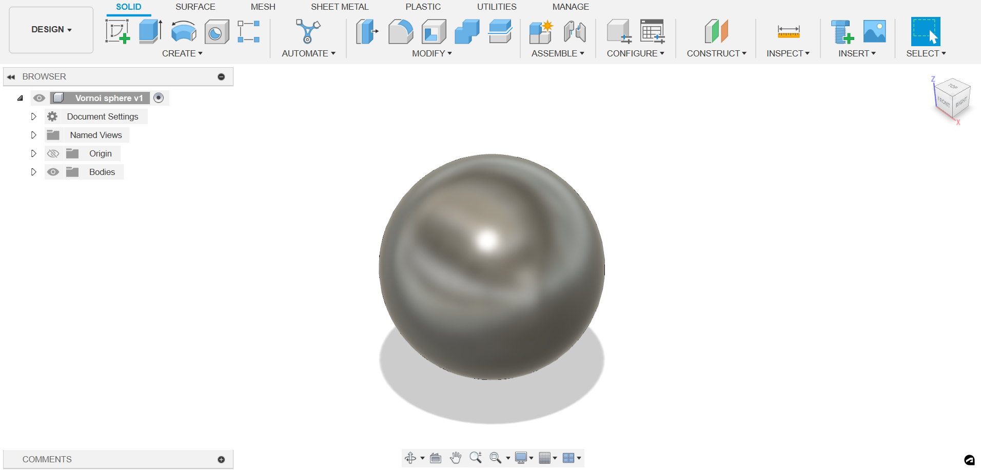
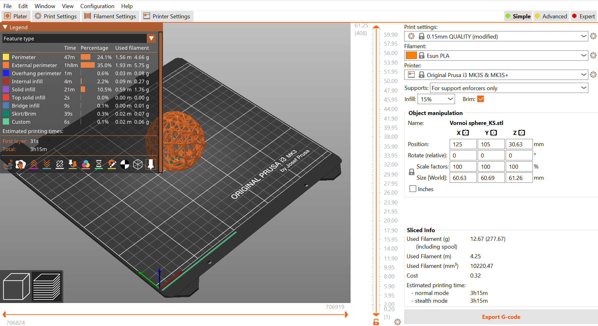
Steps for making an Voronoi sphere:
- First, make a sphere in Fusion 360.
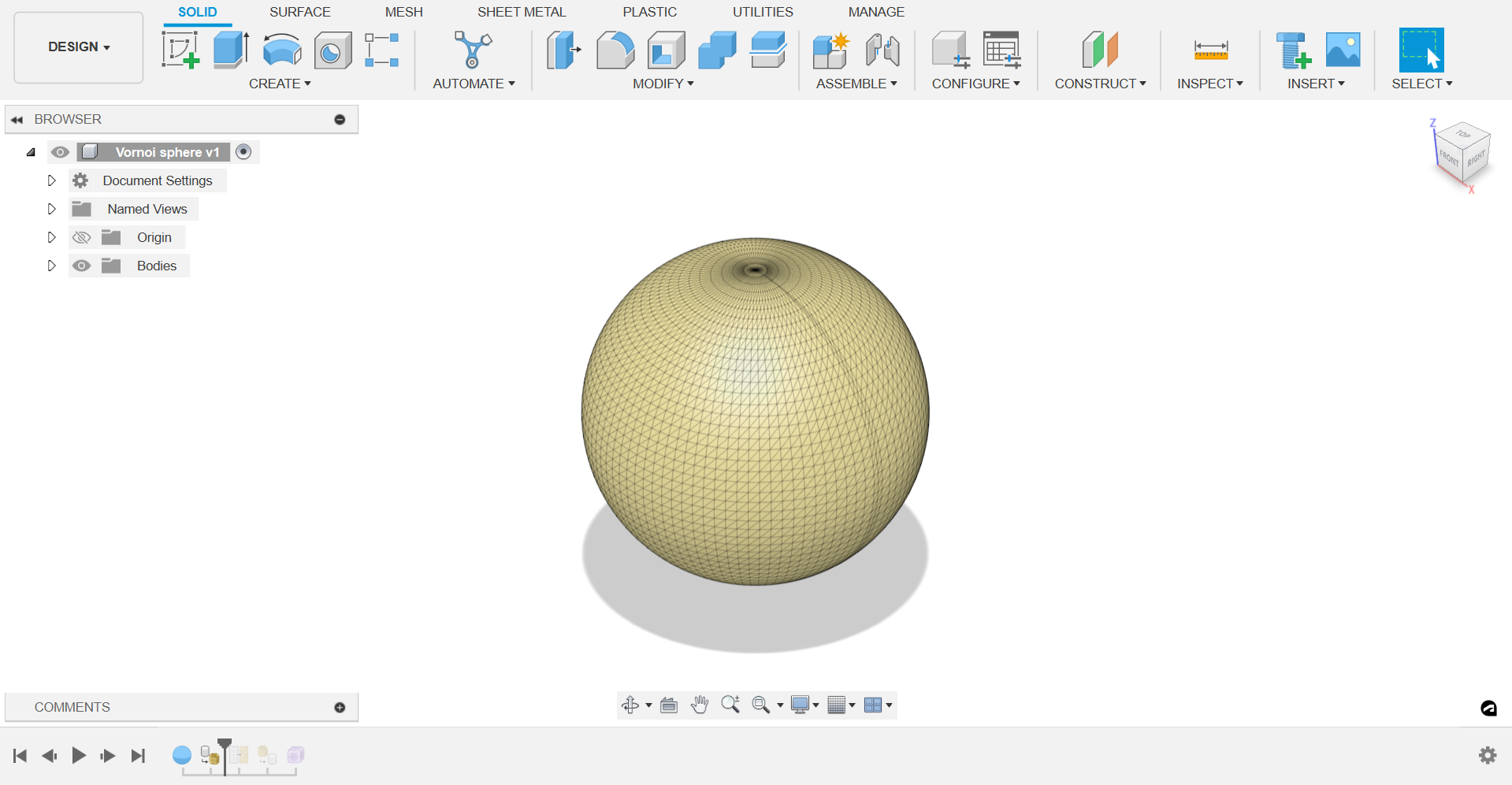
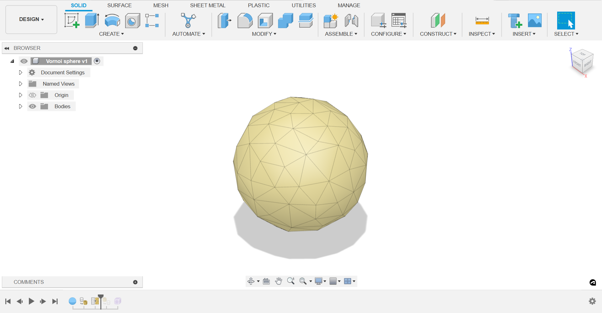
- Go to the mesh option and select the structure and create tessellate and reduce patterns.
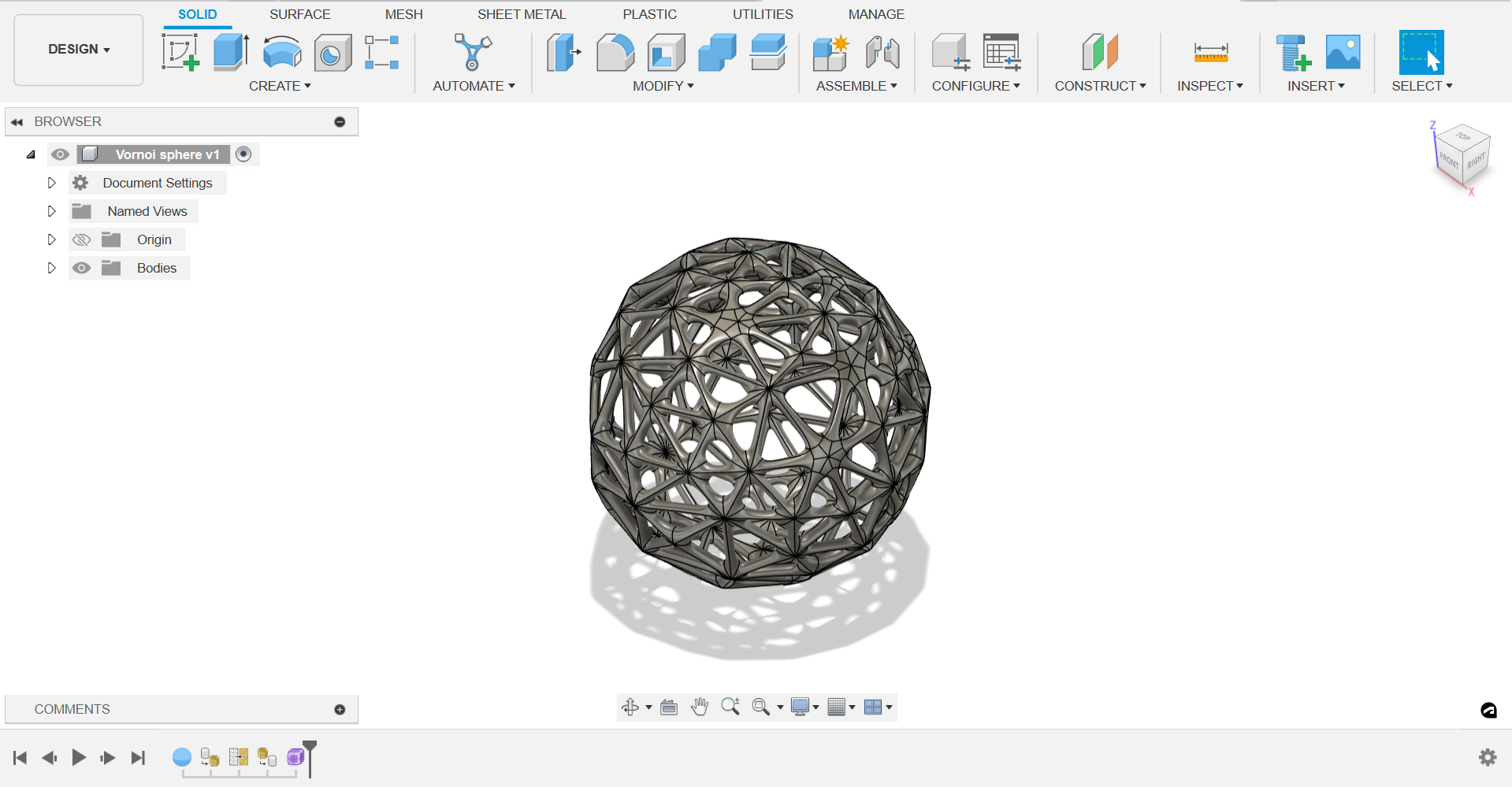
- Select all edges and make it to pipes with smooth edges.
Settings on Prusa Slicer:
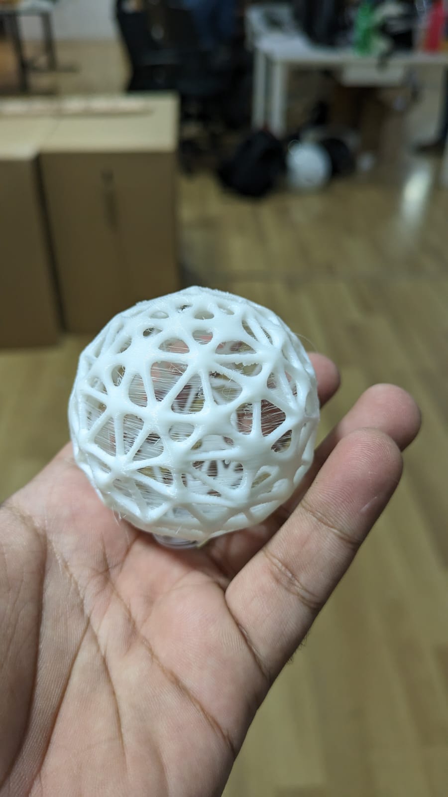
Resulting printed sphere looked something like this:
Exploring Print in Place:
Print-in-place patterns are designs created for 3D printing that are intended to be printed as a single, contiguous piece, with moving parts or intricate features that are already assembled or integrated into the design. This eliminates the need for assembly after printing, making the process more efficient and convenient. One popular example of a print-in-place pattern is the sweep slingy, which features rotating components that are printed as part of the main structure.
Here are some key features of print-in-place patterns:
- Single-piece Design: Print-in-place patterns are designed to be printed as a single, unified object, with all components and moving parts integrated into the structure. This eliminates the need for assembly, reducing post-processing time and effort.
- Moving Parts: One of the defining characteristics of print-in-place patterns is the presence of moving parts that are designed to function within the constraints of the 3D printing process. These moving parts may include hinges, gears, sliders, or rotating components that are engineered to move freely once printed.
- Precision Engineering: Print-in-place patterns require precise engineering to ensure that the moving parts are properly aligned and functional straight off the print bed. This often involves careful consideration of tolerances, clearances, and material properties to achieve smooth movement without the need for additional post-processing.
- Design Flexibility: Despite the constraints imposed by the 3D printing process, print-in-place patterns offer a high degree of design flexibility, allowing for the creation of complex geometries, intricate mechanisms, and customizable features that enhance both form and function.
Now, let's outline the steps to create a sweep slingy in Fusion 360:
- Conceptualization and Sketching: Begin by conceptualizing the design of the sweep slingy, including the overall shape, size, and functionality. Sketch out the keychain's form and identify the components that will rotate or move within the print.
- Modeling in Fusion 360: Launch Fusion 360 and create a new design document. Use sketching and modeling tools to create the 3D geometry of the keychain, incorporating features such as the main body, attachment point for the keyring, and any rotating components.
- Designing Rotating Mechanism: Design the rotating mechanism of the sweep slingy, ensuring that it operates smoothly and efficiently within the constraints of the print-in-place process. This may involve creating gears, bearings, or other mechanisms that enable rotation without binding.
- Adjusting Clearances and Tolerances: Fine-tune the design to accommodate the tolerances required for print-in-place manufacturing. Ensure that there is adequate clearance between moving parts to prevent interference during printing and operation.
- Testing and Iteration: Before proceeding to printing, simulate the movement of the rotating components within Fusion 360 to verify functionality. Make any necessary adjustments to the design based on the simulation results.
- Exporting for 3D Printing: Once satisfied with the design, export the model as an STL file, ensuring that it is optimized for 3D printing. Consider factors such as layer height, infill density, and support structures to achieve optimal print quality.
- Printing: Load the STL file into your 3D printer's slicing software and configure the print settings according to your printer's specifications. Start the printing process and monitor the print carefully to ensure that the moving parts are printed correctly and function as intended.
- Post-Processing: Once the print is complete, carefully remove any support structures and clean up any rough edges or imperfections. Test the functionality of the rotating components to ensure that they move freely without obstruction.
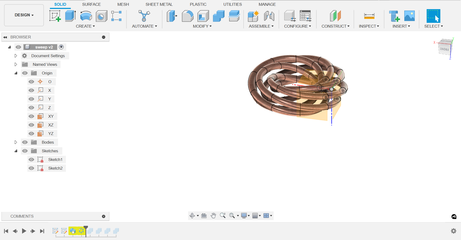
I designed a complex single loop design using fusion 360:
First, I created a hexagon and created 6 circles with a dia of 12 mm on its vertices.
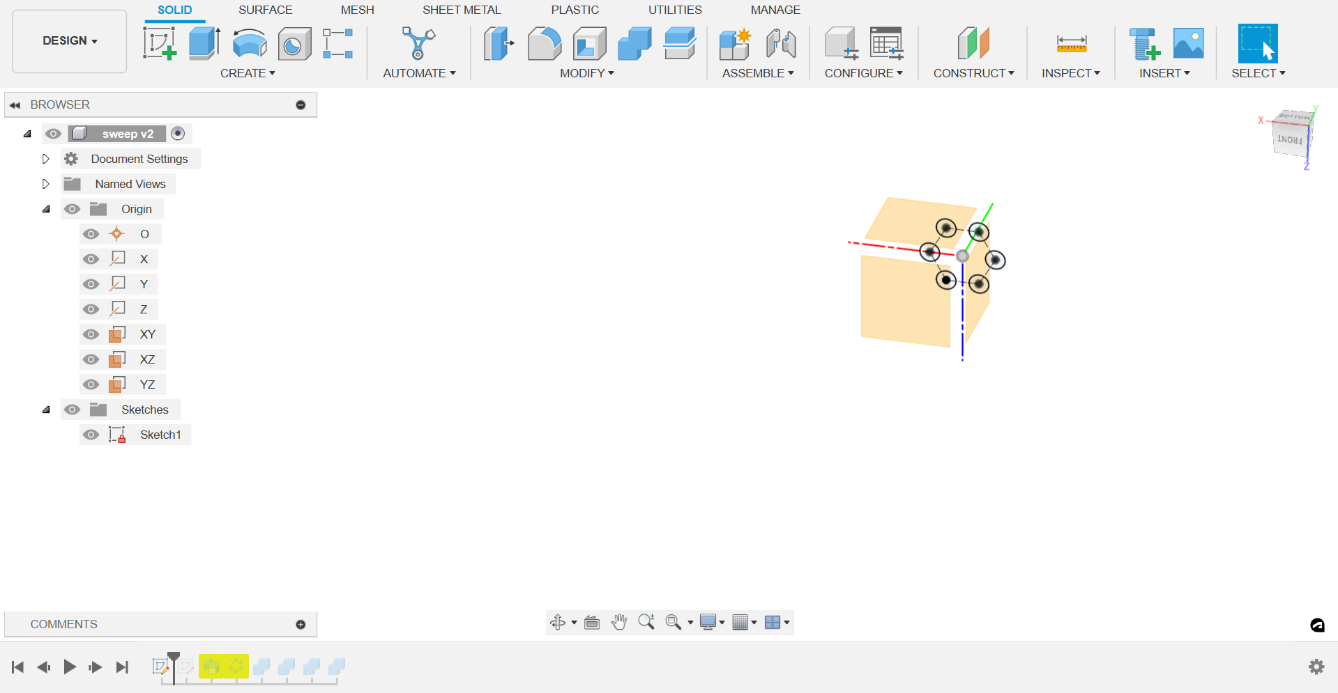
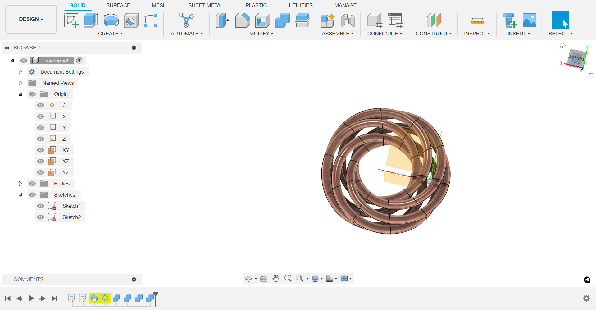
As against the geometry created on the XZ plane, I created a circle on XY plane, to plan the path. Using the sweep tool, I selected the circles on the vertices and gave distance as 0.1 units each and number of units to be 5.
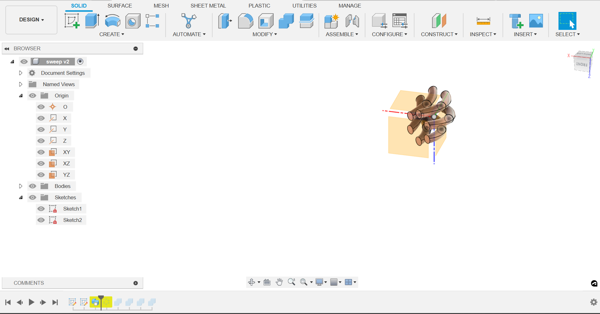
.
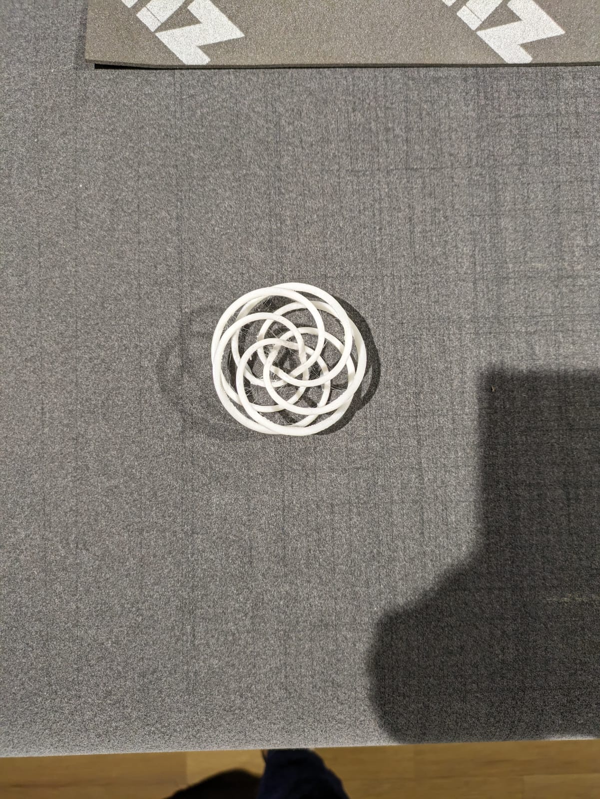
Then I combined it as a single body.
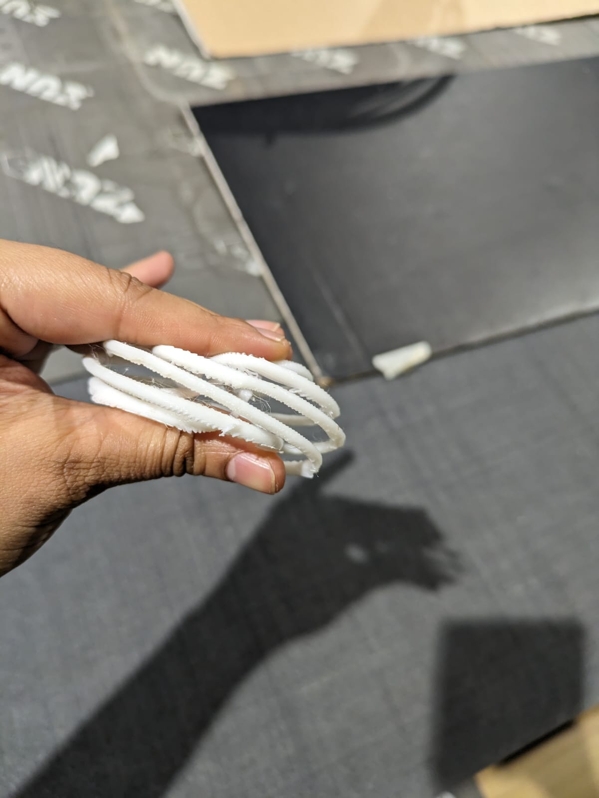
Resulting printed file looked something like this.
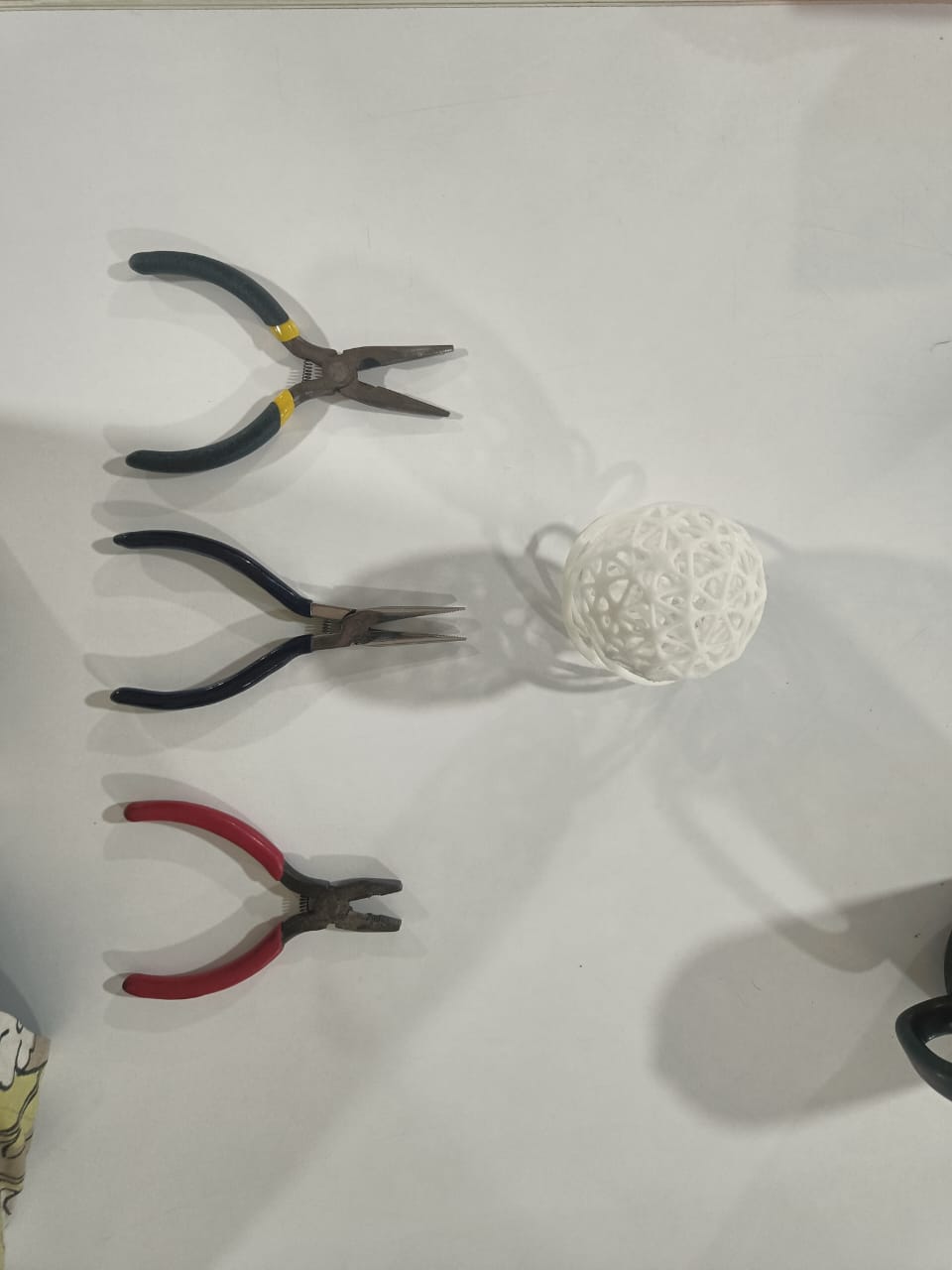
My post processing tools:
3D Scanning using Artec Leo 3D scanner:
Artec Leo is the only wireless and fully standalone professional 3D scanner designed to make scanning as easy and effortless as possible. With the new NVIDIA Jetson TX2 processor onboard, 5” HD built-in display and battery, it’s the ultimate all-in-one 3D scanning solution for fast, accurate, and high-quality data capture.
It may be small, but it is mighty. Leo’s new NVIDIA Jetson TX2 chip runs at more than twice the power of its predecessor, while using less than 7.5 watts of power to give you guaranteed accuracy.
This link has all the models created using Artec leo. I explored this for some inspiration.
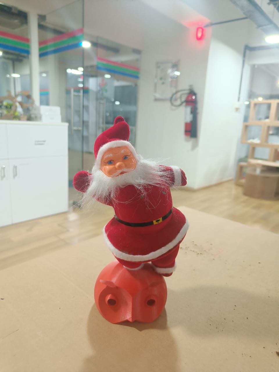
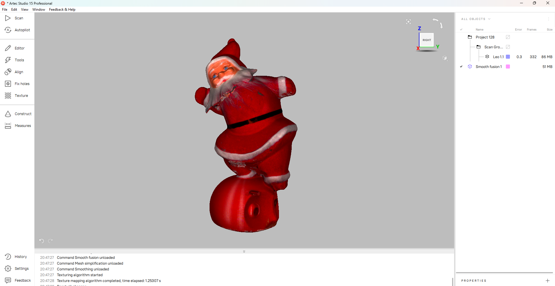
I created a new project and scanned the object of a santa claus mounted on an owl head.
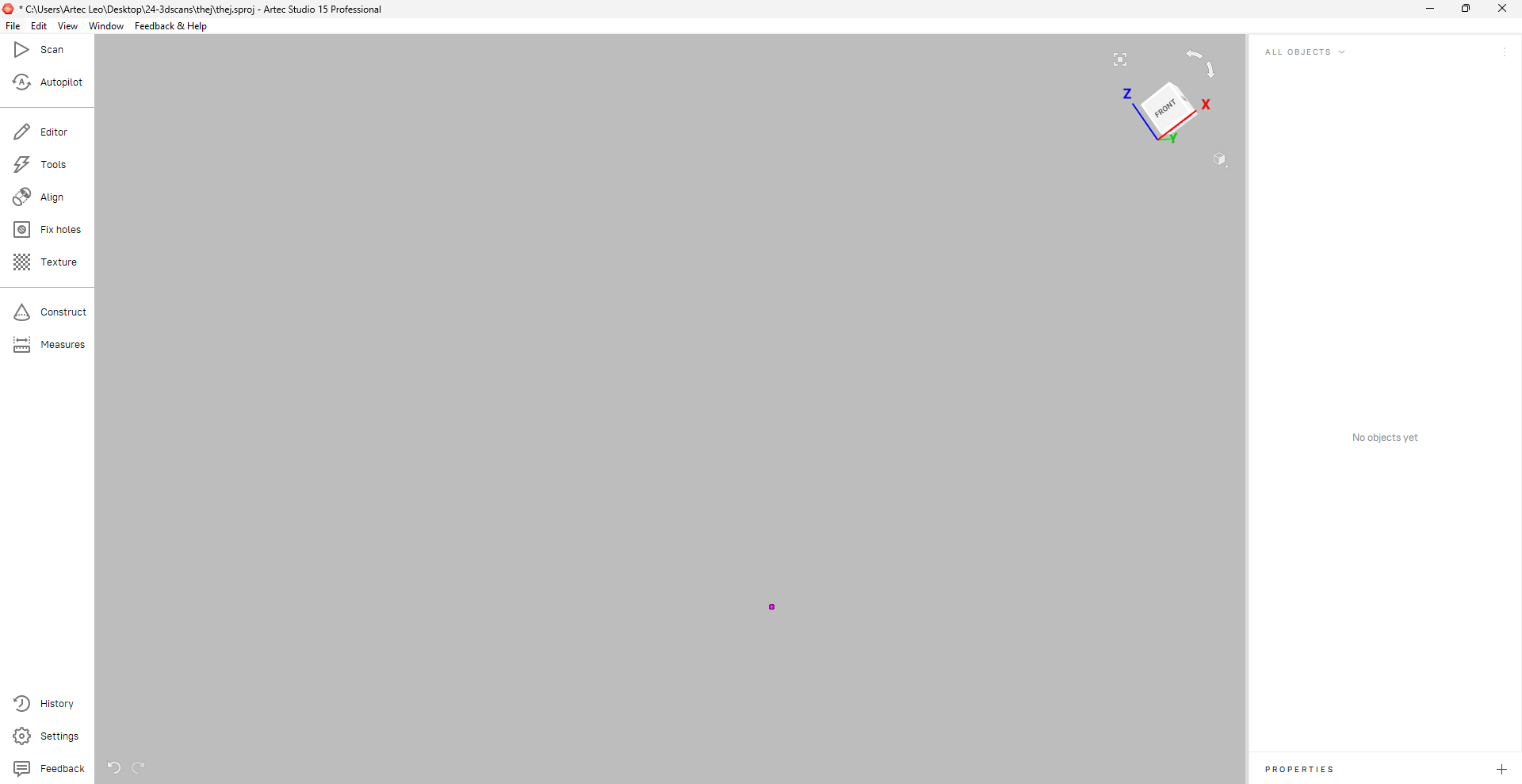
Here’s the software interface.
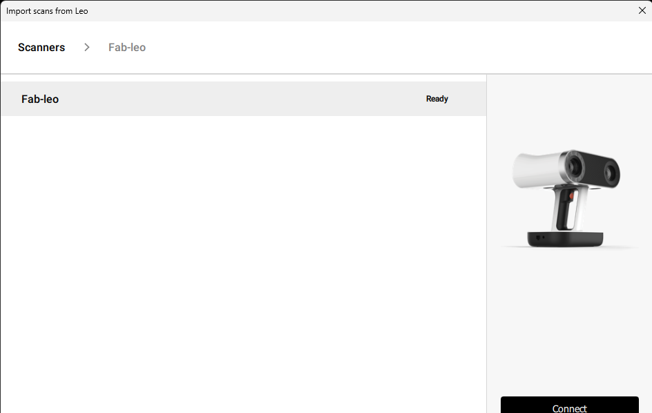
Then, we connected the scanner to the computer.
Then, I chose my project “Project 128” from the Artec interface.
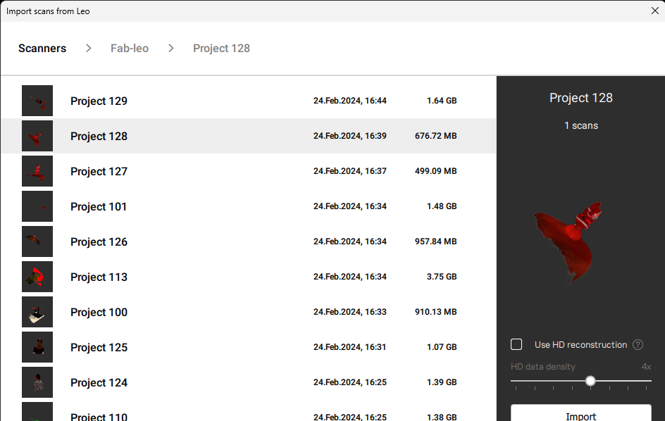
The original file in Artec interface.
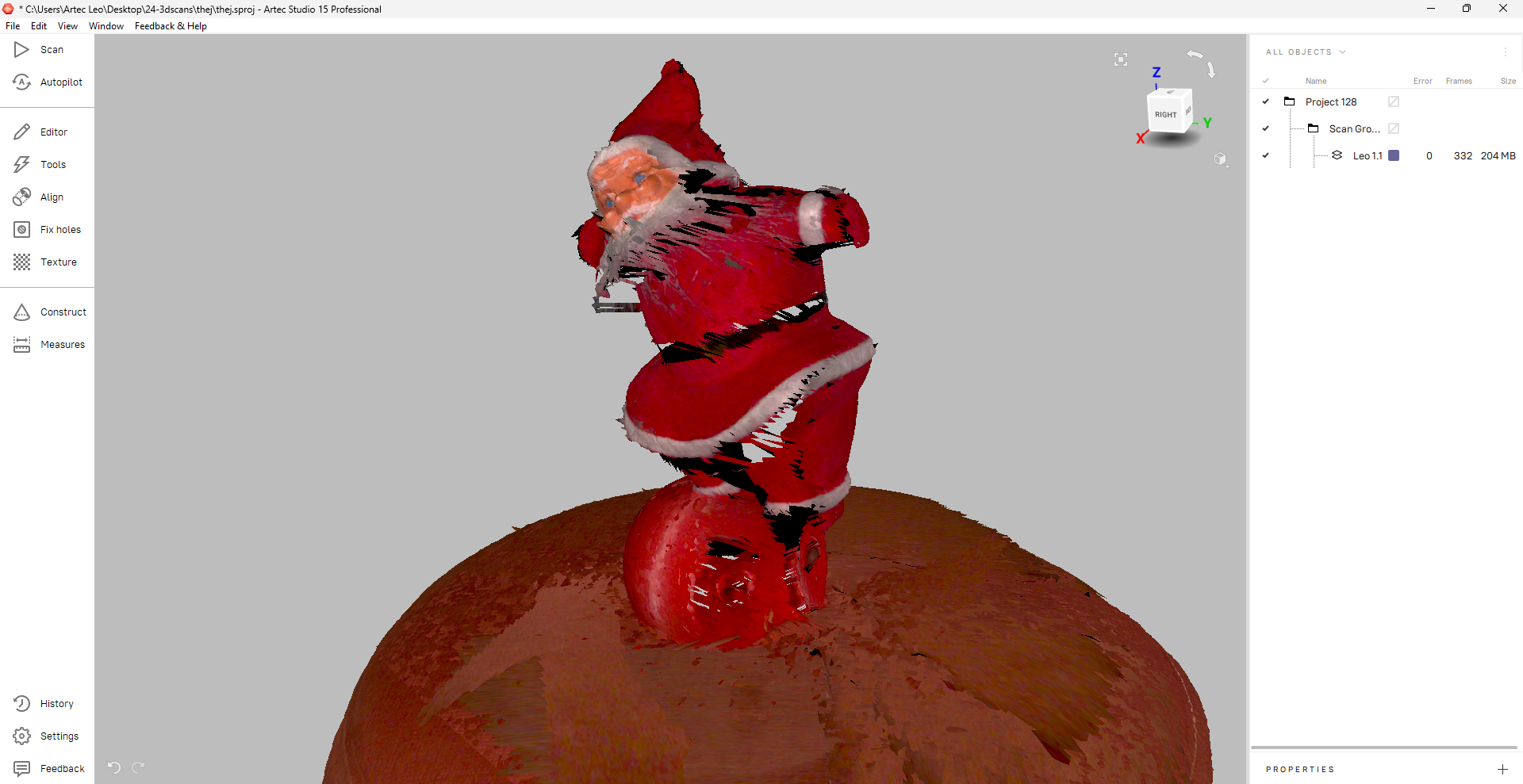
I used the base removal option from editor and removed the base.
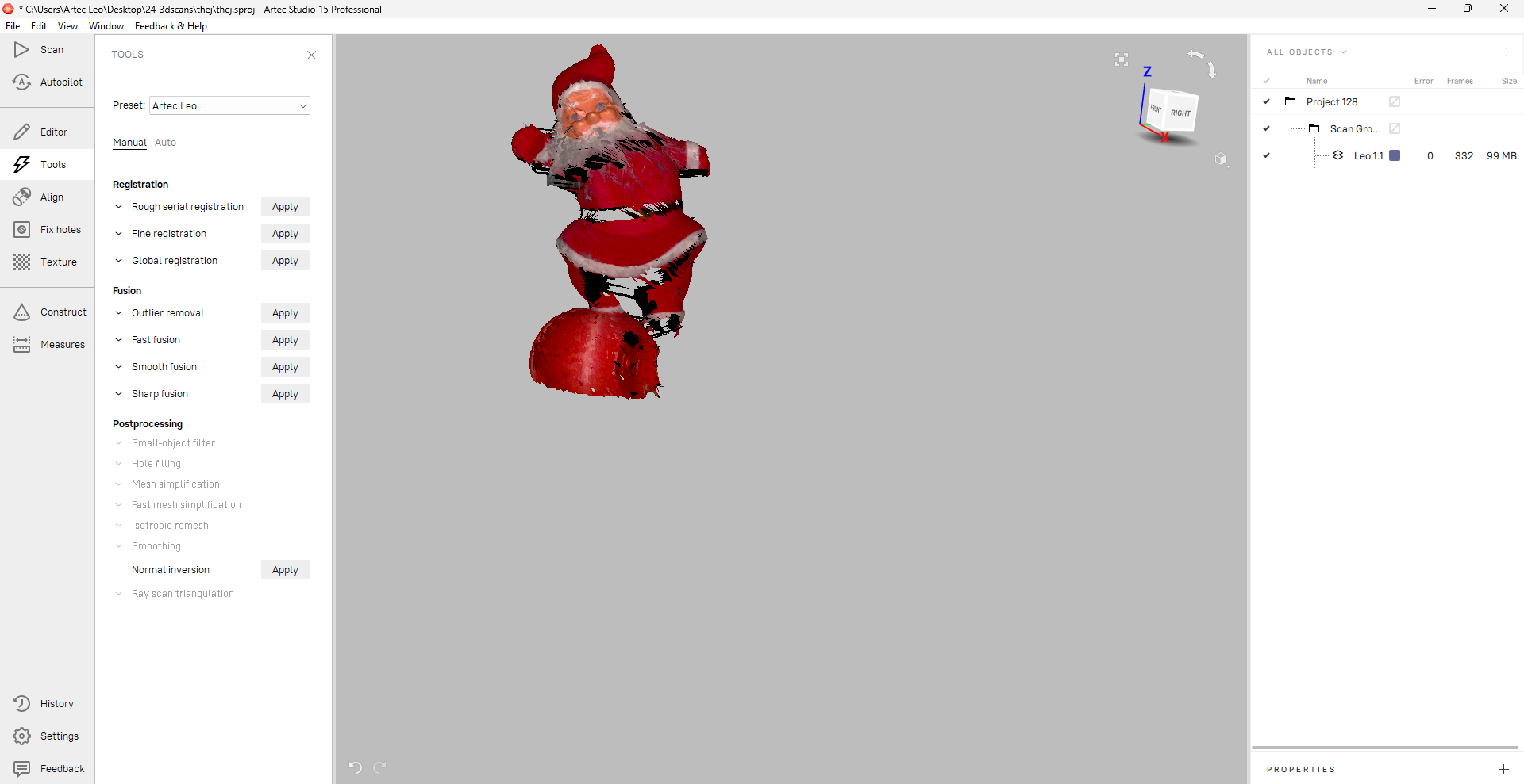
Then, I performed fine registration, global registration and smooth fusion to get a result like this.
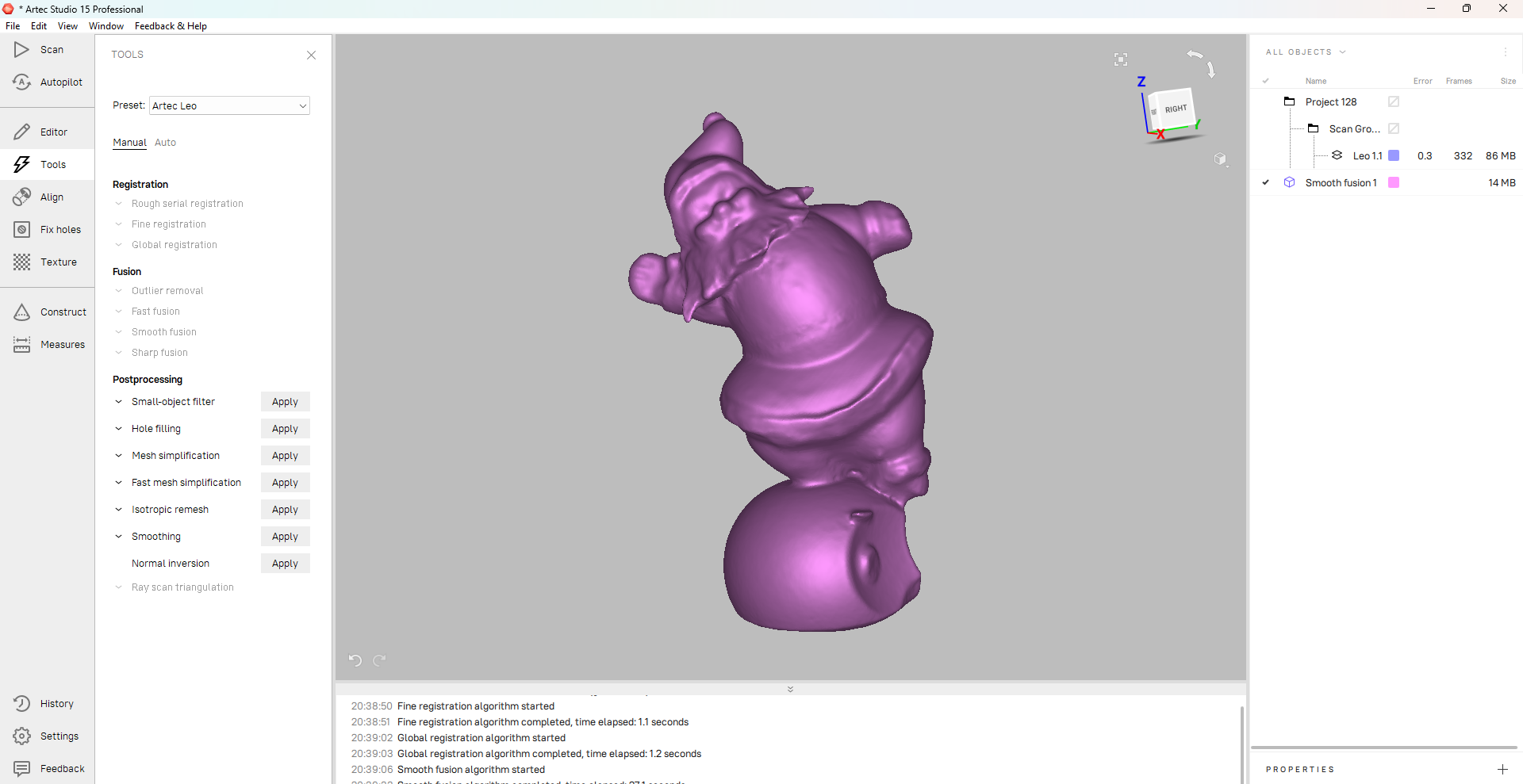
Here’s the final resulting file.
Exploring other types of 3D printing:
Stereolithography (SLA):
SLA 3D printers use light-reactive thermoset materials called “resin.” When SLA resins are exposed to certain wavelengths of light, short molecular chains join together, polymerizing monomers and oligomers into solidified rigid or flexible geometries.
In the context of SLA printing with Formlabs machines, the post-curing process might be what you're referring to. Post-curing is essential for parts printed with clear resin to achieve the best mechanical properties and highest possible clarity.
Here's a general guide on using a Formlabs machine with clear resin and the post-processing steps, which may align with what you're asking:
Printing Process with Formlabs Machine and Clear Resin
- Design Preparation: Use CAD software to design your part. Ensure the design is optimized for SLA printing, considering factors like supports, orientation, and resolution.
- PreForm Software Setup: Import your design into Formlabs' PreForm software. Use the software to orient the part, generate supports, and slice the model into layers. PreForm will also estimate the print time and amount of resin needed.
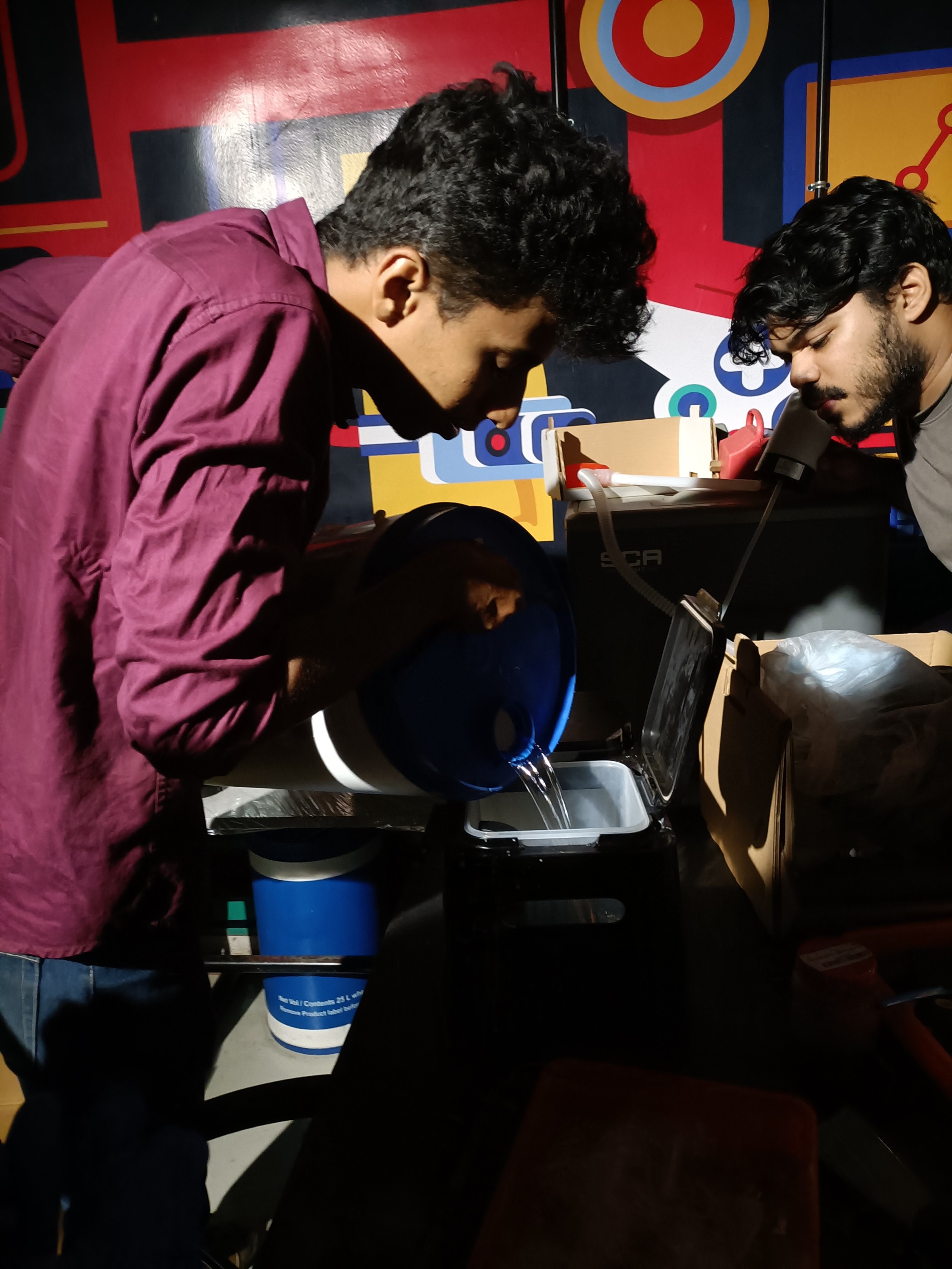
- Printer Preparation: Ensure the Formlabs printer is clean, the resin tank is filled with clear resin, and the build platform is secured.
- Printing: Send the job to the printer through PreForm. The printer uses a laser to cure the resin layer by layer, building your part from the bottom up.
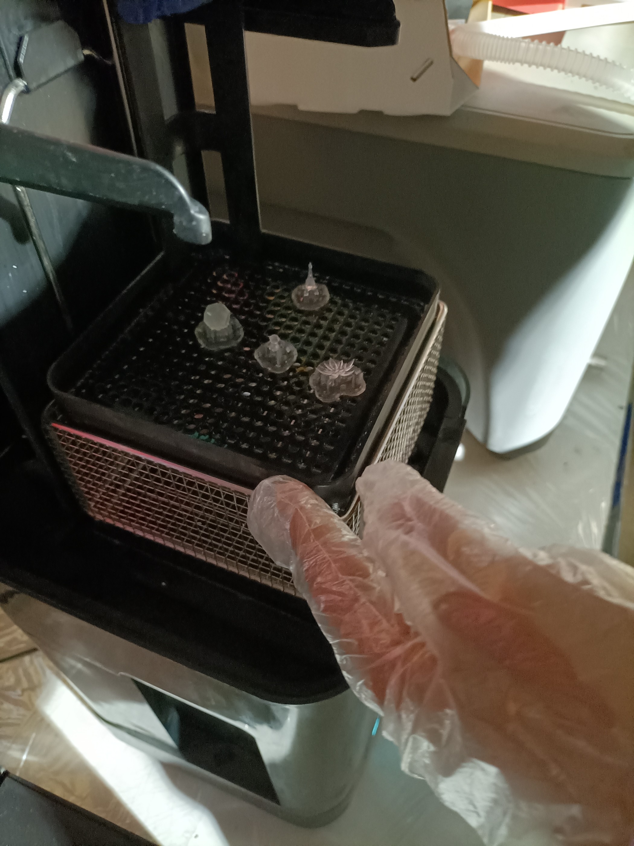
- Removal: Once the print is complete, remove the build platform from the printer and use a scraper to gently detach the part from the platform.
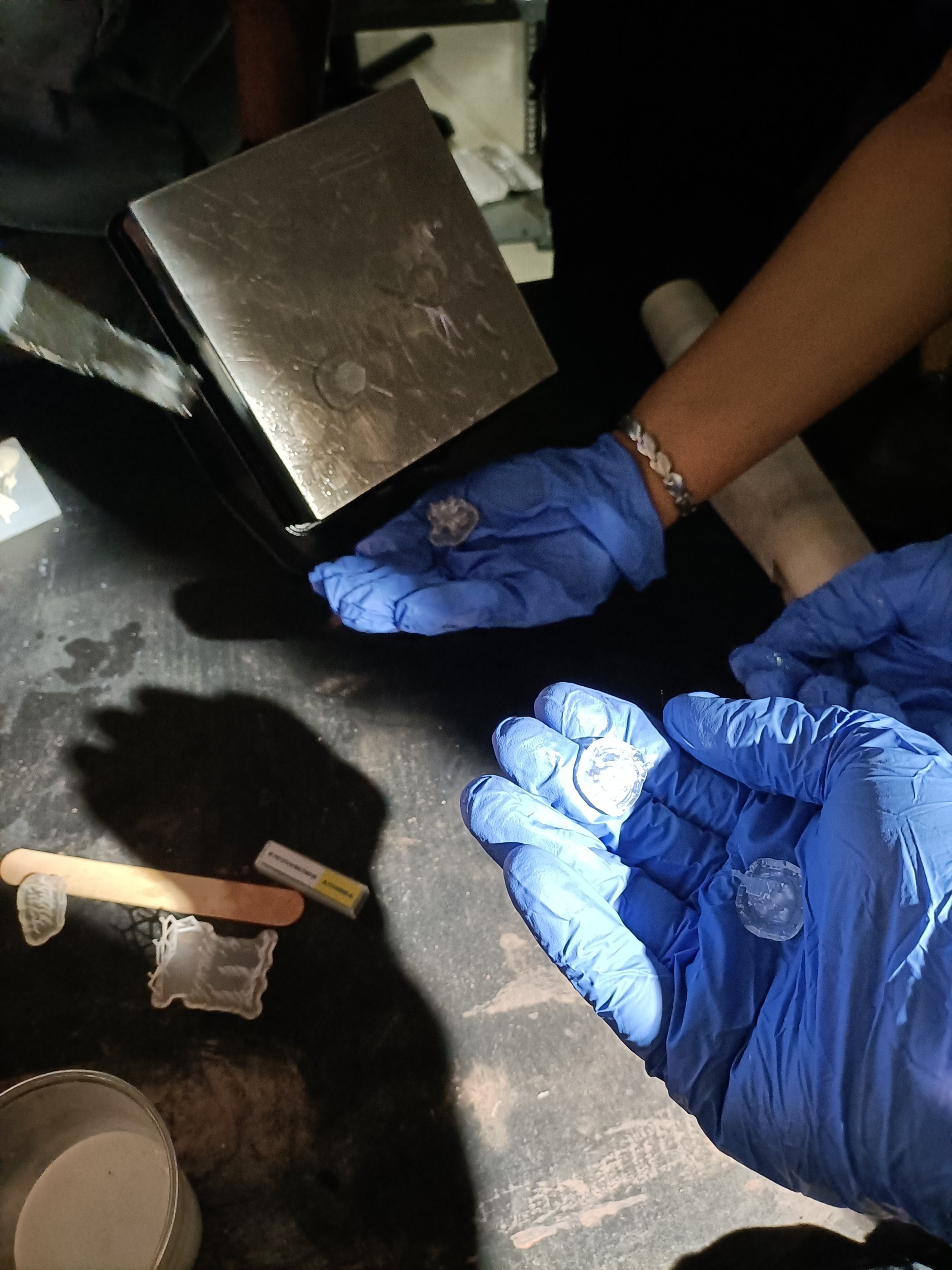
Post-Processing Steps
- Washing: Immerse the printed part in isopropyl alcohol (IPA) to wash away any uncured resin. Formlabs recommends using their Form Wash or a similar setup for a timed wash.
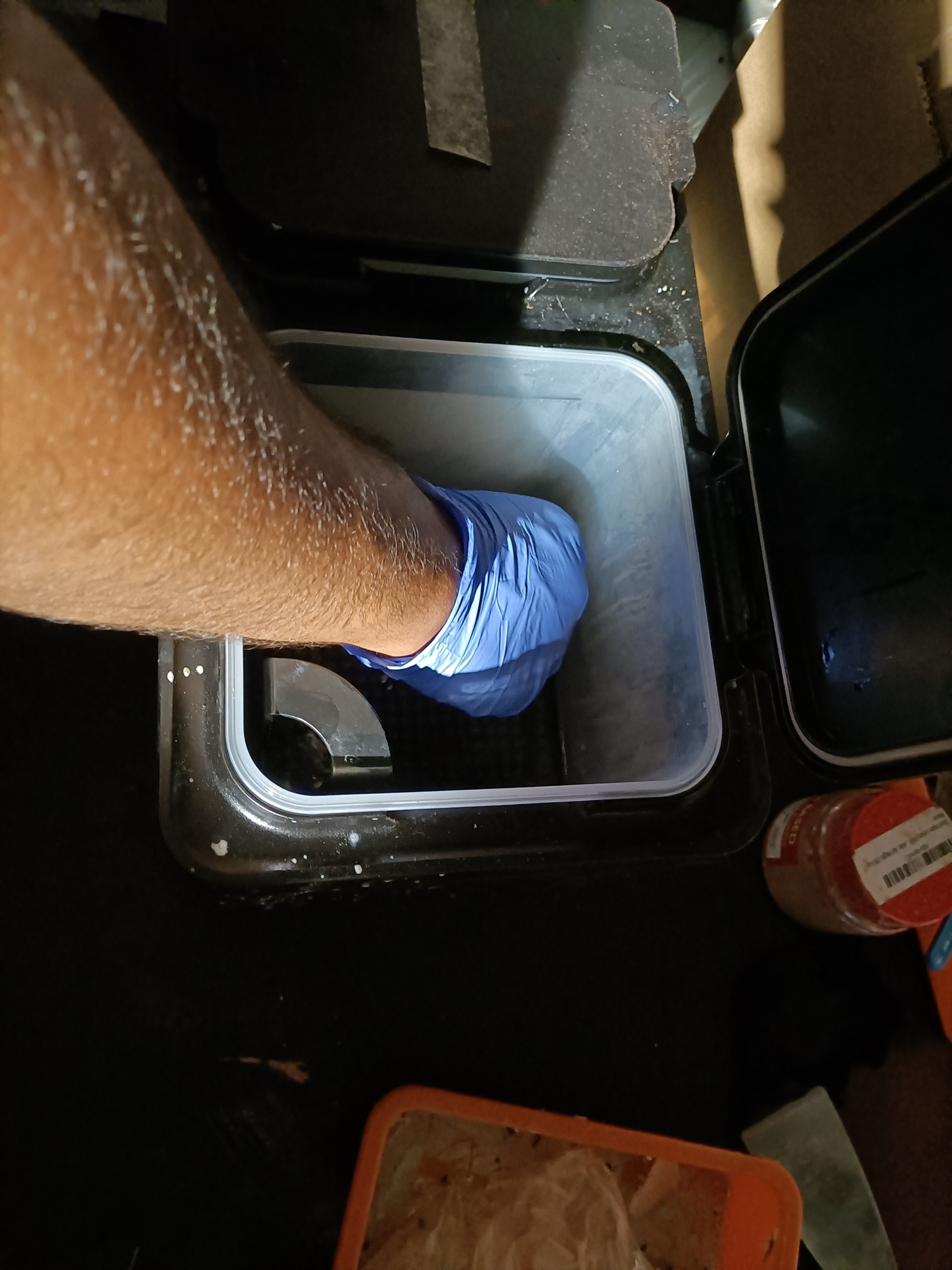
- Support Removal: After washing, remove the support structures. You can use flush cutters for this task, being careful not to damage the part.
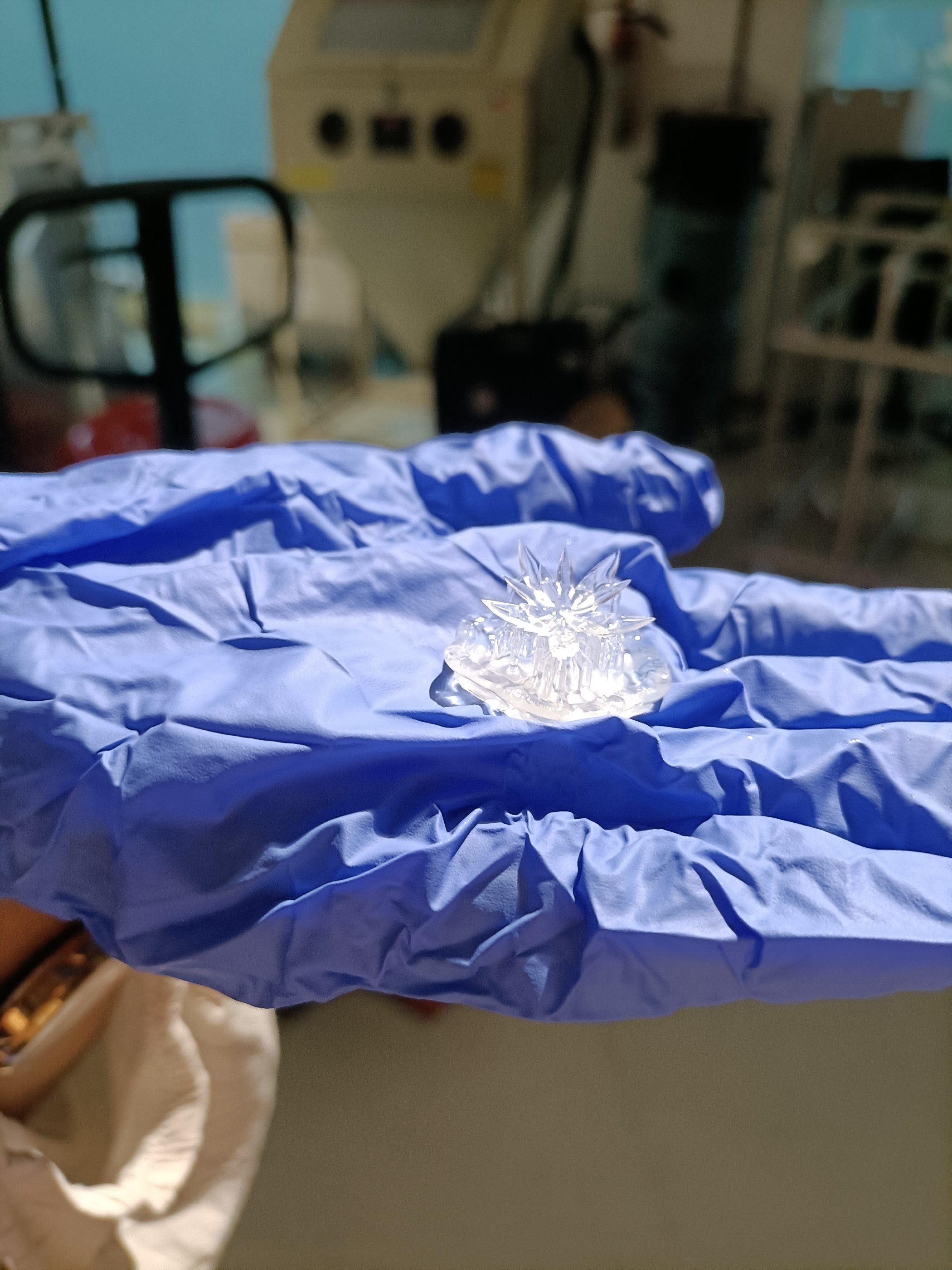
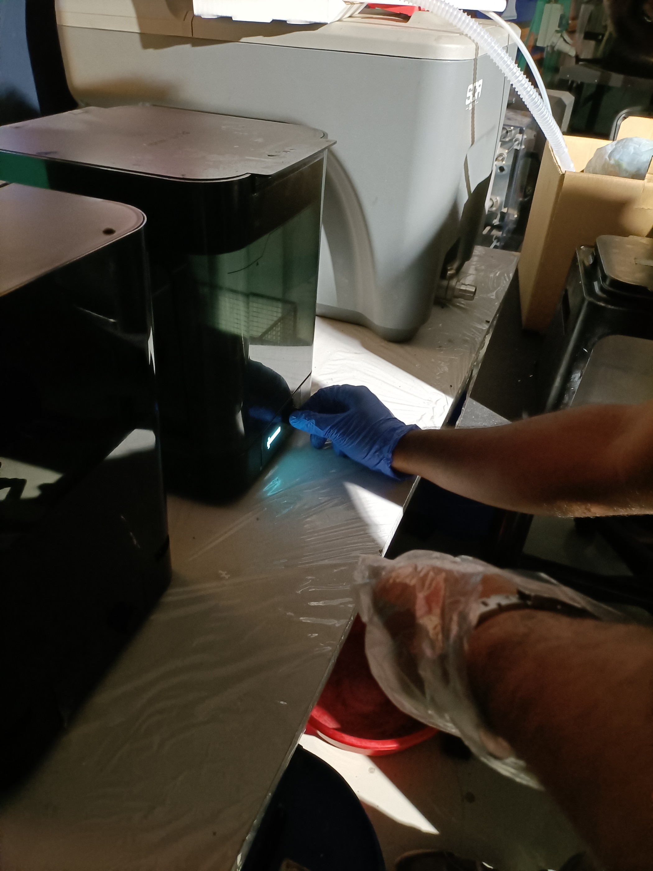
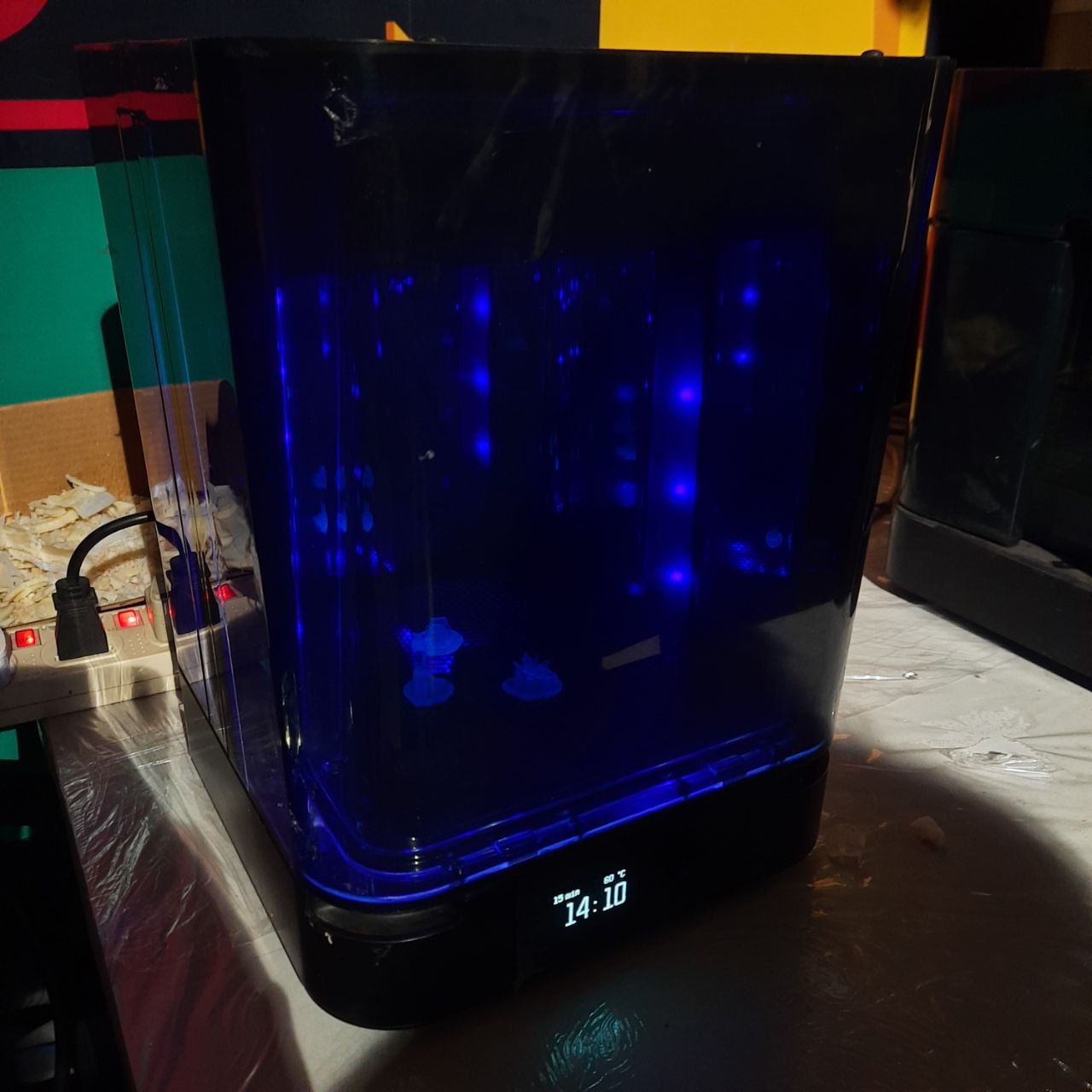
- Post-Curing: Expose the part to UV light to fully cure the resin. This can be done using Formlabs' Form Cure or a similar UV curing chamber. Post-curing improves the part's mechanical properties and stability. The time and temperature for post-curing can vary, but Formlabs provides recommended settings for clear resin.
- Polishing: For clear resin parts, achieving transparency is often a goal. After post-curing, you may sand the part with progressively finer grits of sandpaper and then polish it to achieve a clear finish. Applying a clear coat can also enhance clarity and protect the surface.
- Inspection and Testing: Finally, inspect the part for any defects and test it as needed for your application.
It's important to follow safety guidelines throughout this process, including wearing gloves when handling uncured resin and parts, working in a well-ventilated area, and protecting your eyes from UV light during post-curing.